


 Lead 10.16mm(0.4\") with Sensor")
 Lead 5.08mm(0.2\") with Sensor")
 Lead 2.54mm(0.1\") with Sensor")
 Lead 12.7mm(0.5\") with Sensor")
 Lead 8mm(0.314961\") with Sensor")
 Lead 12.7mm(0.5\") with Sensor")
 Lead 6.35mm(0.25\") with Sensor")
 Lead 6.35mm(0.25\") with Sensor")
 Lead 2.54mm(0.1\") with Sensor")
 Lead 2.54mm(0.1\") with Sensor")
 Lead 4mm(0.15748\") with Sensor")
 Lead 2mm(0.07874\") with Sensor")
 Lead 12.7mm(0.5\") with Sensor")
 Lead 6.35mm(0.25\") with Sensor")
 Lead 2.54mm(0.1\") with Sensor")
 Lead 10.16mm(0.4\") with Sensor")
 Lead 5.08mm(0.2\") with Sensor")
 Lead 2.54mm(0.1\") with Sensor")
 Nema 34 Stepper Motor & Driver & 60V Power Supply")
 Nema 34 Stepper Motor & Driver & 60V Power Supply")
 Nema 34 Stepper Motor & Driver & 60V Power Supply")
 Nema 23 Stepper Motor & Driver")
 Nema 34 Stepper Motor & Driver & 60V Power Supply")
 Nema 34 Stepper Motor & Driver")
 Nema 23 Stepper Motor & Driver")
 Nema 34 Stepper Motor & Driver")
 Nema 34 Stepper Motor & Driver")
 Nema 34 Stepper Motor & Driver & 60V Power Supply")


Stepper motors are a common option in motion control applications. As they can achieve precise positioning without the need of position feedback if operated correctly. The stepper motor linear actuator uses a unique and advanced technology to integrate the screw pair and stepper motor in one unit. Customers do not need to install couplings when using them, which not only saves installation space, but also effectively improves the efficiency of system assembly. Stepper motor linear actuators can therefore be an economical solution for the accurate positioning of linear movements.
Based on these linear actuators, many different structures can be built in relation to them. Stepper motor linear actuators can usually be divided into three types according to their construction: external, non-captive and captive.
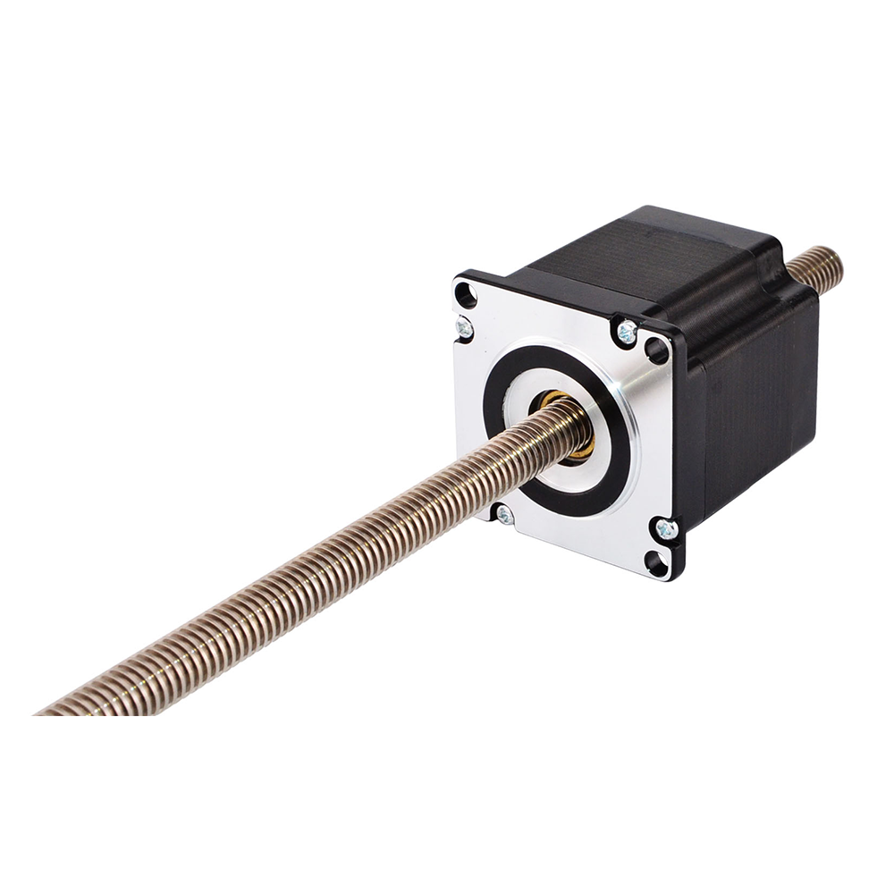
Features and applications of external linear actuator
The external linear actuator can replace the cylinder in some applications, with the advantages of precise positioning, controllable speed and high accuracy. External linear actuators are generally chosen for linear sliding systems with strokes of 60 to 500 mm. However, a long screw can also cause problems, as the actuator and screw resonate at certain positions in the stroke, thus causing noise. The use of drive technology such as subdivision and setting acceleration and deceleration can reduce noise, and the design of the screw end with bearing support can also help to reduce noise.
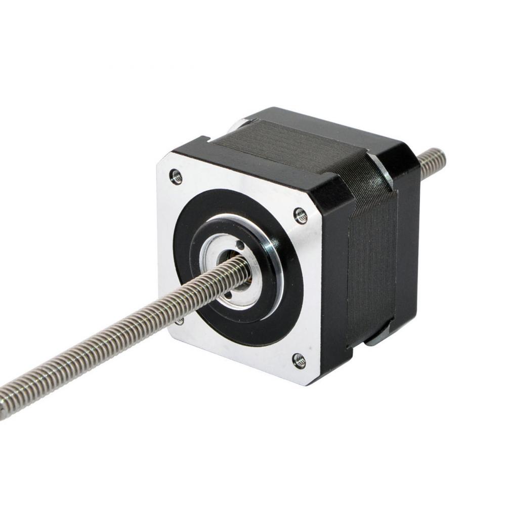
Features and applications of non-captive linear actuator
The non-captive linear actuator has its unique advantages, which are mainly reflected in the following 3 aspects.
-
Allowing for greater system mounting errors
The non-captive linear actuators are typically used for applications with a stroke of 30-200mm. The advantage of non-captive linear actuators over external linear actuators is that they allow for greater mounting coaxial tolerance errors. The screw and nut of a linear module are likely to lead to system stalling if they have poor parallelism with the guideway. Although the nut allows a certain radial clearance, this is not sufficient for the entire module, whereas the radial clearance of the nut of a non-captive linear actuator allows for a tilt of the screw within 1゜. The structural characteristics of its design allow for greater system mounting errors.
-
Not limited by the critical speed of the screw
When a external linear actuator is selected for high-speed linear motion, it is usually limited by the critical speed of the screw. However, when using a non-captive linear actuator, the screw is configured to fixed and anti-rotated, and then the motor is set to drive the slider of the linear guideway. As the screw is stationary, it is not limited by the critical speed of the screw when achieving high speeds.
-
Saving installation space
The non-captive linear actuator, owing to its design with the nut built into the motor, does not take up additional space in the length of the external screw. Multiple motors can be mounted on the same screw, the motors cannot pass through each other and their movements are independent of each other. This makes it the suitable choice for applications where space requirements are more stringent.
The advantage of non-captive linear actuators, as mentioned above, is that they allow a certain amount of installation misalignment, but they are not only suitable for applications with slightly large installation errors, but also for applications such as piston pumps where precise positioning and installation is required. The self-centering design of the screw allows it to be guided to accommodate installations with different centers and also to avoid lateral forces on the piston seal.
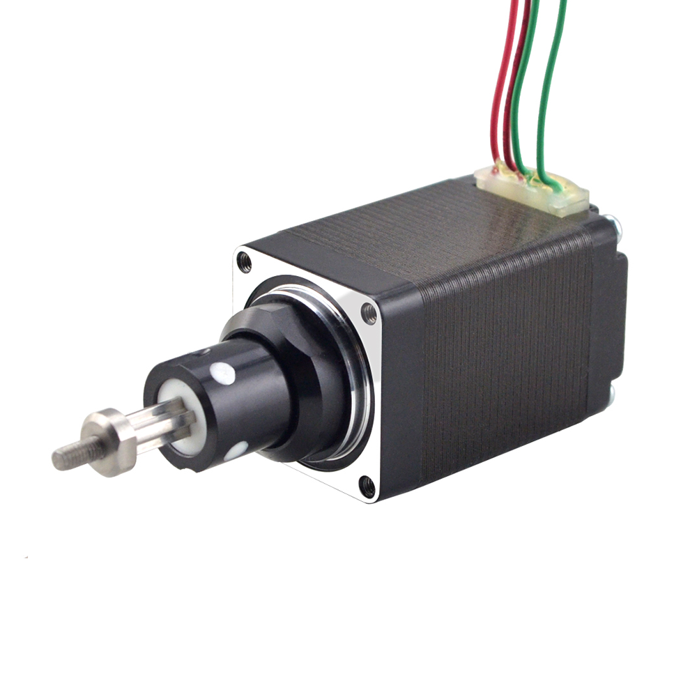
Features and applications of captive linear actuator
Captive linear actuators are advisable for applications with short stroke requirements, such as less than 50 mm, and where a nut or screw anti-rotation mechanism cannot be provided. The advantage of captive linear actuator is that it is compact and does not require an anti-rotation mechanism. The spline sleeve at the front of the motor is molded and cannot withstand large lateral forces, as it is mainly designed to limit the screw's rotational action against the motor. The ball spline design can be used for applications that require lateral loading, as the recirculating ball design of the spline sleeve increases the lateral loading capacity of captive linear actuators.