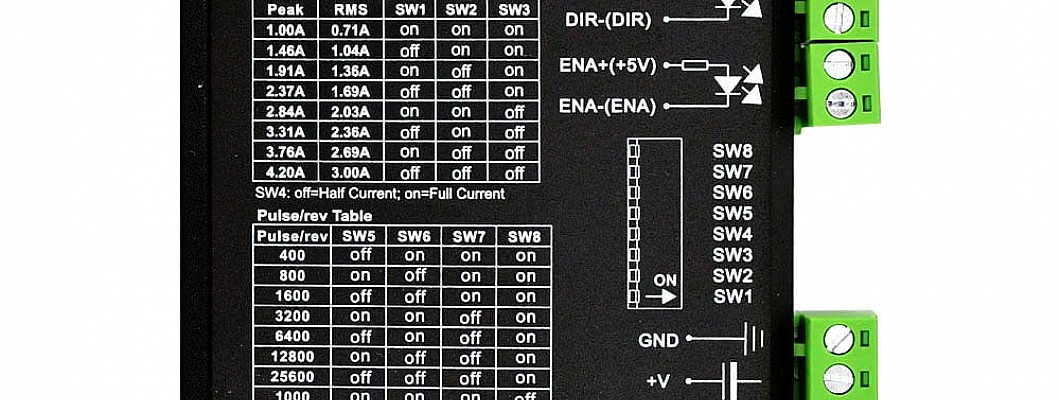
How to Set the Subdivision of the Digital Stepper Driver
1.In the terms of setting the value of a digital stepper driver, the higher the subdivision value, the higher the control resolution on common sense. For two-phase motor, the calculation method of pulse equivalent is as follows: pulse equivalent = lead screw pitch ÷ subdivision number ÷ 200.
2.Takeoff Speed: This parameter corresponds to the take-off frequency of the stepper motor, meaning that the motor can start working without acceleration. The proper selection of this parameter can improve the processing efficiency and avoid the low-speed section with poor motion characteristics. However, the value is set too large, it will cause stuffy cars. So a margin must be left.
3. Uniaxial acceleration: Used to describe the acceleration and deceleration capacity of a single feed shaft. This index is determined by the physical characteristics of the machine tool, such as the quality of the moving part, the torque of the feed motor, resistance, cutting load, etc. The greater this value, the more efficient it will be, meaning the less time will be spent in acceleration and deceleration during exercise. General speaking, in terms of stepper motors, this value should between 100 and 500. While for servo motors, it can be set between 400 and 1200. When setting, the value should small and the motor should do repeated exercise for a while. Pay attention to it. If no abnormalities can be observed, then the value can be increased. If any abnormalities are found, the value should be reduced and leave a 50%~100% insurance balance.
4. Bend acceleration: Used to describe the acceleration and deceleration capabilities of multiple feed axes when they are in motion. It determines the speed of the machine tool in circular motion. The larger this value is, the higher the allowable speed of the machine tool in circular motion is. The value of lathe which is consisted of stepper motors should kept within 400 to 1000. And the value of servo motors should be 1000 and 5000. If it is a heavy lathe, the value should be adjusted smaller. When setting, the value should small and the motor should do repeated exercise for a while. Pay attention to it. If no abnormalities can be observed, then the value can be increased. If any abnormalities are found, the value should be reduced and leave a 50%~100% insurance balance.
5.According to the position where the three null-point sensors are installed, the user can set the parameter to return back to the mechnical origin. When the user sets correctly, he can run the Operation menu.
6.Setting the automobile refueling parameters and judging whether it is right. If it is correct, the parameters should be adjusted to meet the practical demand.
7.Then the user should judge whether the setting value of the electronic gear matches that figure of pulse equivalence. The user can make a mark on any axis of the machine tool, which can be seen as the working zero point. By inputting the command directly, jogging or manual operating, the axis can move a fixed distance. A vernier caliper can be used to measure whether the actual distance is consistent with the distance displayed in the software.
8.The last step is to measure whether there is pulse loss. The user can adopt a method like this: he can use a sharp knife to mark a point on a semi-finished product and set the point as the origin. The Z axis should be raised and set to 0. And then make the lathe exercise repeatedly. But be careful, the practical speed of these three axes should be limited.


