Controlling stepper motors is a broad topic and this article is a simplified beginner's guide to use stepper motors. It covers the basics of how stepper motors operate. Its purpose is to help beginners get stepper motors running.
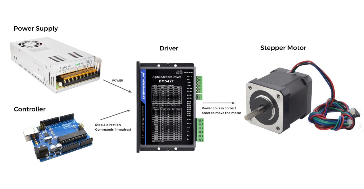
To drive a stepper motor you usually need the following equipment:
- Stepper motor
- Stepper motor driver
- Controller
- Switching power supply
How to choose the proper equipment
1. Stepper motor
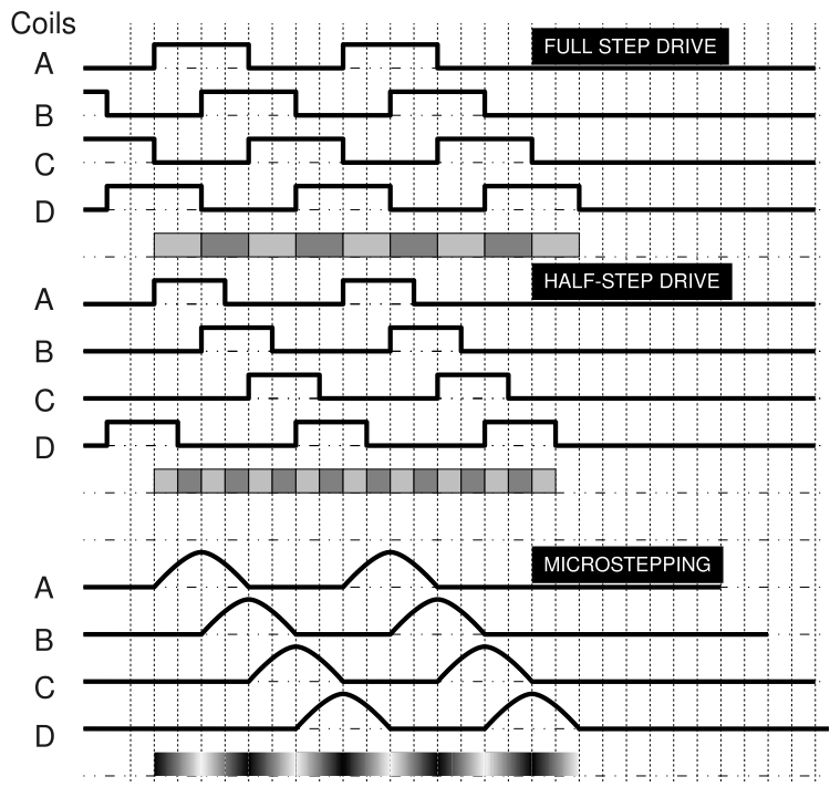
A stepper motor is an electromagnetic device that moves in discrete steps. It has several coils which are organized into phases. When each phase is energized in turn, it causes the motor to step. With stepper motors, you can achieve precise positioning and speed control. There are three main ways that a stepper motor can be driven. These three driving ways are full-step drive, half-step drive, and microstepping.
You need to select the right stepper motor for your speed and torque requirements based on data such as frame size, step angle,holding torque, rated current, number of leads, and unipolar or bipolar. I will explain some of these important concepts next.
Nema: Nema is not a standard for the electrical characteristics of stepper motors. It is simply a standard for faceplates and mounting holes to facilitate motor interchangeability. For example, the "17" in "NEMA 17" refers to the faceplate size, which in the NEMA standard is the "number" of NEMA divided by 10 inches. Thus, a NEMA 17 motor has a faceplate that is approximately 1.7 inches wide.
Step angle: The step angle indicates the rotation angle of the stepper motor when the control system sends a stepping pulse signal. The step angle of the general two-phase stepper motor is 0.9°/1.8°, the three-phase stepper motor is 1.2°, and the five-phase stepper motor is 0.72°.
Speed-torque: The operating performance of stepper motors at low speeds is of more practical importance. Stepper motors typically operate at speeds of 300 to 600 rpm. Considering that the user uses a mechanical reduction device to carry the load, the normal speed of the motor is often selected at tens of rpm to provide sufficient torque for the motor. In this case, the motor provides high force, high efficiency and low noise.
As for the vibration problem, it should be solved by increasing the drive subdivision. Subdivision is the drive's control of the motor after each pulse sent by the upper computer is subdivided by a multiplier set by the drive. Simply put, it is the reduction of the motor's step angle by the subdivision multiplier.
Motor speed calculation formula: Motor speed (unit: RPM) = pulse frequency (unit: Hz)*60/subdivision.
Holding torque: The holding torque is the amount of torque required to move the motor one full step while the coils are energized and the rotor is stationary. The stepper motor winding is energized even if the rotor itself is stationary. This is to maintain the load in place while stationary.
Shaft style: You need to know the physical shape of this motor shaft in order to match your stepper motor to gears, pulleys, and other external connections such as shaft couplers. There are several common shapes. Additionally, the length of the shaft needs to be considered.
Some common types of shafts are listed below:
- Round Shaft - round shaped shaft
- "D" Shaft - a "D-shaped" shaft that is useful for mounting gears with set screws.
- Geared Shaft - a shaft with a gear etched into it.
- Lead-screw shaft - a shaft shaped like a screw, used for building linear actuators.
Rated Current: This refers to the peak current. This is a useful specification because it allows you to select a suitable driver and power supply for your stepper motor.
2. Stepper motor driver
Stepper motor driver generally has to be used in conjunction with stepper motor, so when you buy a stepper motor, it is best to match a suitable driver at the same time to reduce the trouble later.
Almost all stepper motor drivers use a standard protocol to control the motor. It uses 3 pins:
ENABLE - The driver will only operate when the ENABLE pin is pulled LOW or HIGH, depending on the driver.
DIRECTION - When LOW, the motor will rotate in one direction and when HIGH in the other direction. This is related to how you connect the motor.
STEP - Whenever the STEP pin goes from low to high, the stepper will make one step (or microstep, depending on the driver's settings).
3. Controller
Stepper motor controller is capable of sending high speed pulse signals and is programmable. PLC, microcontrollers and other devices are common controllers on the market.
4. Switching power supply
It is better to use switching power supply for stepper motor. It has a strong anti-interference ability and allows a wide range of fluctuations. The current needs to be selected according to the size of the load. It is necessary to leave a certain amount of margin. For example, the stepper motor current is 3A, the control load current 2A, the switching power supply should be selected 6A to 8A.
Types of stepper motors, drivers and wiring schemas
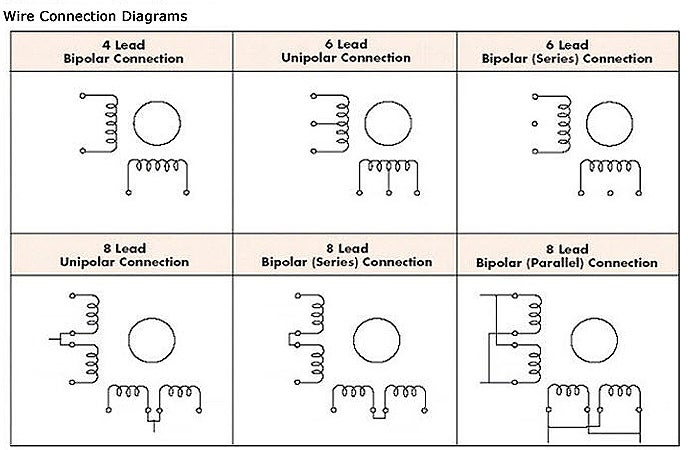
Bipolar and unipolar motors
Stepper motors come in two different types: unipolar and bipolar. The biggest difference between them is that both different types have their own winding arrangements, and their respective winding arrangements are what will affect the way their stepper motors are driven.
A 4-wire motor can only be driven by a bipolar driver. A 5-wire motor can only be driven by a unipolar driver because the center tap is tied together internally. 6-wire and 8-wire motors can use both driver types because you can decide how to connect them externally.
In essence, unipolar and bipolar motors work in exactly the same way. The electromagnets open in a sequential manner, inducing the central motor shaft to rotate. They differ in how the coils inside the motor are energized.
A unipolar motor achieves polarity reversal through the center tap of the coil, but only energizes half of the coil at the same time, so it has less torque available.
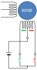
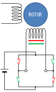
A bipolar driver uses an H-bridge circuit to actually reverse the current flowing through each phase. By alternately energizing each phase, all coils can be used to turn the motor.
A two-phase bipolar motor has two sets of coils. Two-phase bipolar motors have four wires, two for each phase. For some motors with flexible wiring, it is possible to run the motor as bipolar or unipolar.
Unipolar drive
Bipolar drive
Constant voltage driver vs. Constant current driver
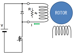
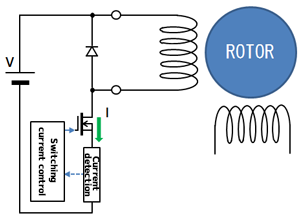
There are two types of motor drives: unipolar and bipolar, and two methods of controlling the current flowing through the motor: constant voltage and constant current. Constant voltage driver provides a fixed voltage to the motor, while constant current driver ensures a constant current to the motor by manipulating the voltage. Constant voltage driver is also known as L/R driver. Constant current driver is also known as chopper driver.
Due to the torque and speed limitations of L/R drivers, constant current drivers are currently more popular. Constant voltage drivers are most often used for unipolar stepper motors.
When using constant voltage drivers, the voltage rating of the motor is mostly irrelevant for practical applications. Therefore, do not be influenced by stepper motors based on very low voltage ratings. An important value to note is the rated current. STEPPERONLINE's stepper drivers are currently constant current drivers!
A constant current driver can run a stepper motor at a much higher voltage than the motor's rated voltage. The higher voltage allows current to flow through the stepper motor faster, which allows it to turn faster and get more torque. The driver keeps the current in the motor below a fixed value, which prevents the motor from burning out. The fixed current is usually set by a trim pot on the drive board. This allows you to change the maximum current depending on the torque needed and the rated current of the motor specification. In addition, higher voltage means less heat.
Constant voltage drive
Constant current drive
How to wire a stepper motor to a driver
You need to figure out which wires make up the coil pairs. Here’s three ways to figure this out.
1.You can use a multimeter and measure the resistance between the wires coming from the stepper motor. If you have a reading, it's a pair. If not, it's not a pair.
2.In addition, if you don't have a multimeter, turn the motor while touching the wires. Whichever combination makes it difficult to move the motor, it's a pair.
3.Of course, it's not practical to sort out all possible combinations of connections with an ohmmeter or by feel. It is still easiest to connect the motor according to its datasheet. Assuming you don't already have one, then read the model number off the motor and search online. You may need to contact the supplier to get the data sheet for the motor. STEPPERONLINE provides the appropriate data sheet, or you can contact customer service if anything else is still unclear.
The following diagram shows several different winding arrangements: